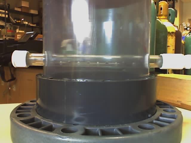
Side-view of the lysimeter base- Note this is a pre-fitting of the drainage tube before the base gravel an high density polyethylene liner (HDPE) were sealed underneath the drainage holes in the tube.
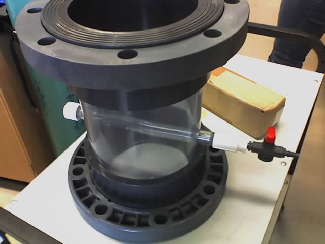
Lysimeter base showing the stop-cock valve outlet, as well as a screw-cap rear entry access to the drainage tube, allowing access to the eventual clog material.
Downward view of the base with the HDPE liner sealed under the drainage tube with a layer of geotextile fiber between the liner and the drainage tube.
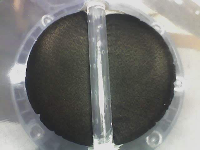
Layer of gravel filled at a height of 3 inches over the HDPE liner.

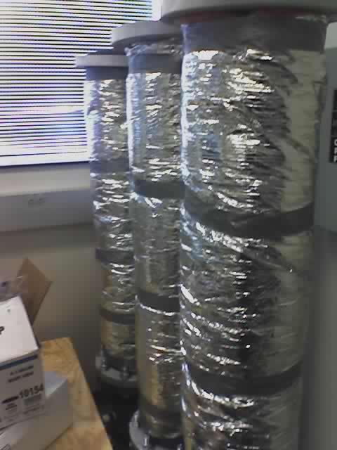
The lysimeter mid-sections were attached to the bases, and insulated with fiber glass duct insulation.
Garbage preparation and mixing before packing into the lysimeters.

View of garbage packed into the transparent prototype lysimeter with an 8 inch overlay of gravel.
![]()